|
|
|
Usuarios conectados
Actualmente hay 5672 visitantes y
1 usuarios online. |
|
Productos
|
|
Información
|
|
Destacado
|
|
|
 |
|
|
No hay comentarios de productos.
TK-5400
CIRCUIT DESCRIPTION
6. Transmitter System
6-1. Microphone Amplifier
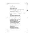
The signal from the noise canceller amplifier (control unit IC3) passes through the MIC changeover circuit (Q711), the mute switch (Q713) and the AGC circuit, and goes to the microphone amplifier IC (IC602). When an accessory speaker microphone (SP-MIC) is not installed, the microphone switching terminal (MSW/CTS) goes high and the microphone changeover switch (Q711) turns on. When the SP-MIC is installed, the MSW/CTS is connected to GND in the SP-MIC, Q711 turns off, the internal microphone is muted and only the external microphone input is supplied to the microphone amplifier of the TX-RX unit. The AGC circuit consists of IC602 (1/2), D600, D601, Q600 and Q601. The AGC is operated by using the current obtained by detecting positive or negative polarity of the audio signal amplified by IC602 (1/2) and controlling the positive (+) and negative (�) level of the amplifier. The transmit audio signal output from IC602 (2/2) is input to pin 3 (AINL) of the codec IC (IC608) and converted from analog to digital. The digitalized transmit audio signal undergoes AGC processing, pre-emphasizing, filtering, vocoding (in APCO mode), and returns to the codec IC (IC608). The signal is converted from digital to analog and an analog signal (C4FM base band signal in APCO mode) is output from pin 16 (AOUTR). The audio signal that is DSP-processed by the codec IC (IC608) and DSP (IC611) passes through the analog switch (IC706) and amplifier (IC606, IC604) and goes to the D/A converter (IC605). The audio signal whose maximum deviation is adjusted by the D/A converter passes through the AF switch (Q202 is off in TX mode) and goes to VCO modulation input. The audio signal whose modulation balance is adjusted by the D/A converter passes through a buffer amplifier (IC607) and goes to VCXO modulation input.
EXT. MIC (IC703) MUTE MAIN IC3 MIC Q710 SUB (CONT) MSW/CTS IC605 IC706 SW IC606 AMP IC604 AMP D/A Q202 SW 5R BUFF AMP IC607 VCXO X201 L702 VCO Q711 SW MIC N/C AMP SW ATT Q600 Q601 AMP IC602 CODEC IC608 D600 D601 DET IC611 DSP
6-2. Noise Cancelling Microphone Circuit
The two signals from INT MIC (Main & Sub) are fed to the positive (+) input (Sub) and to the negative (�) input (Main) of the IC3. If the same signals is fed to both Main and Sub, the Main signal is terminated at the output of IC3 (pin7). In another words, noise from nearby sources not directly connected to the transceiver enters the Main and Sub input at the same signals and is therefore canceled out. When a signal is only fed to the Main and there is no signal at the Sub, IC3 (pin 7) outputs the Main signal as it is. In other words, only the voice audio of the operator to the Main MIC is input to the Main so that �N/C� switch is set to �L�, transistor Q14 is turned off and the Sub microphone also is turned off and the operation is same as above.
6-3. Drive and Final Amplifier
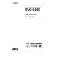
The signal from the T/R switch (D101 is active) is amplified by the pre-drive (Q101) and drive amplifier (Q103) to 50mW. The drive amplifier output is amplified by the RF power amplifier (Q1, Q2, Q3) to 3W (1W when the power is low). The RF power amplifier has two-stage MOS FET transistor. The output of the RF power amplifier is then passed through the Transmit-Receive (TX-RX) antenna switching (D103 is active) and low-pass filter (LPF) and applied to the antenna terminal.
6-4. APC Circuit
The APC circuit always monitors the current flow through the RF power amplifier (Q1, Q2 or Q3) and maintains a constant current. The voltage drop at R101, R102 and R103 is caused by the current flow through the RF power amplifier and this voltage is applied to the differential amplifier (IC101 1/2). IC101 (2/2) compares the output voltage of IC101 (1/2) with the reference voltage from IC605. The output of IC101 (2/2) controls the voltages the VGG of the RF power amplifier to make the both voltages to same voltage. The power high/low switching is carried out by changing the reference voltage. The Q102, Q104 and Q105 are turned on in transmit and the APC circuit is active.
ANT Q101 From T/R SW (D101) Pre DRIVE AMP R101 +B R102 R103 � + Q104 SW IC101 (1/2) � + IC101 (2/2) Q102 SW Q103 DRIVE AMP Q1,2,3 RF POWER AMP VDD VGG D103 TX-RX ANT SW Q105 SW LPF
Fig. 8
Microphone amplifier
REF VOL (IC605)
Fig. 9
Drive and final amplifier and APC circuit 11
|
|
|
> |
|